Bioprocess
Upstream Processing
Figure 8. Porcine


Figure 10. Example fish source
1. Substrate choice & preparation of substrate
Meat most rich in bioactive peptides are bovine and porcine sourced meat, although cattle sources are most abundant in waste, this will make up a large portion of the substrate. Bioactive peptides remain dormant in their parent protein, so the meat must go through a process to release and activate these peptides (Ryan et al., 2011). As previously stated in the rationale, only approximately 2 - 3kg of meat is wasted from porcine sources, while cattle have a much larger portion of wasted meat (80-90kg)(Toldra et al, 2014) . Bovine by-products aren’t very commonly utilized, while porcine by-products are put to use. For example, pig’s blood is commonly utilized in the creation of black pudding otherwise famously known as “blood pudding” as is bovine blood, although porcine blood is more frequently used (FSAI, 2013).
As demonstrated by the literature cited, the peptides that exhibit antihypertensive properties are MNPPK (otherwise known as myanopentapeptide A), ITTNP (otherwise known as myanopentapeptide B), thermolysin, sourced from bovine meat trimmings & cuttings while peptides AKGANGAPGIAGAPGFPGARGPSGPQGPSGPP & PAGNPGADGQPGAKGANGAP from bovine collagen sources (Ryan et al, 2011). Porcine sources are rich in RMLGQTPTK peptides, specifically in the skeletal muscles. Porcine myosin gives rise to both myanopentapeptide A and B, therefore enforcing the suitability of the product. In correlation with the enrichment of the substrate trimmings and cuttings from bovine and porcine sources will be submerged in the blood from the same sources. Alongside the substrate, a brine solution will also be mixed in prior to blending to create a high salt concentration as a means for the Salt Activated Nuclease (SAN) to be at its optimum efficiency. This mixture will be blended in a Robot Coupe R20 triple blade cutter, with a capacity of approximately 20L. This piece of equipment was chosen due to its size, ease of sanitation and ability to monitor the blending of the substrate during the process. While it is an expensive piece of equipment, it is a vital asset and investment into NutriPlus as its speed will cater toward effiency and its ease of sanitation will ensure that staff will understand how to properly clean the substrate.
Alternative substrates
There is an extremely wide variety of meat and meat waste which could be used in place of bovine and porcine sources. Studies have shown the effective use of fish and their muscle proteins as a source of bioactive peptides, alongside using non-meat substrates but still animal by-products such as milk and eggs as a source of bioactives. Of course, we mustn’t forget the chicken industry, a large portion of what makes up the meat industry. So why are we only using bovine and porcine sources? As stated in the rationale, this project aims to solve two main problems: the use of synthetic anti-hypertensive drugs and reducing the abundance of meat waste as it is costly and difficult to dispose of. Bioactive peptides that arise from fish sources give rise to anti-hypertensive bioactive peptides among many others (Bhat et al., 2015), which is fantastic. These bioactives are generally sourced in the meat of the fish, which is generally lacking when the fish by-products are deemed as waste or have no further destination, Using fish as a source is only combatting one problem as opposed to two. In addition to that point, fish, shellfish and molluscs are a major source of allergens. As the bioactives are sourced from meat, a segment of the market is already rejected, therefore using fish would further eliminate a potential segment of the market if they obtained a fish allergen. While there is a plethora of anti-hypertensive bioactive peptides that can be generated from varying types of fish, different varieties of enzymes must be implicated in order to obtain optimum generation of the target bioactive peptides. This does not fit in with our current protocol, but perhaps in the future if fish waste comes into abundance, NutriPlus will consider the use of fish substrates.
Chicken breasts in particular, withhold anti-hypertensive bioactive peptides such as GFHypGTHypGLHypGF but only after the chicken breasts are treated extensively and then hydrolyzed with aspergillus protease. This as a substrate would not be applicable because the chicken breast used is not a by-product of the meat industry that would be soon determined as waste. The chicken breast would be a perfectly good product that would be viable for human consumption. Anti-hypertensive peptides such as FRADHPPL may also be derived from ovalbumin sources found in eggs (Ryan et al, 2011). Similarly to the chicken scenario, eggs are not abundant in waste as beef and pork trimmings. While they may give rise to perfectly functional bioactive peptides, using them would not fully contribute to reducing and reusing the amount of meat waste or animal by-product generated by slaughterhouses and food processing companies.
The upstream processing of our product involves the following:
-
Substrate choice & preparation
-
Cell line
-
Bioreactor
-
Preparation of bioreactor
-
Inoculation
-
Enzyme hydrolysis

Figure 6. Bovine
Figure 7. Bovine (Iveta, 2015)
Figure 9. Robot coupe R20 triple blade cutter (Wards Catering, 2016)
(Scientia, 2014)
(CuriousGang, 2017)
Figure 11. Chicken source (Acuri, 2017)
Figure 12. Egg source (Lourens & Meijerhof, 2017)
2. choice of cell line
It is well known throughout the scientific community that enzymes are expensive and sensitive factors in terms of production and experimentation and vital to many processes. For this bioprocess only two enzymes are utilized for the extraction of bioactive peptides. The first enzyme, SAN, will be utilized in order to decrease the viscosity of the meat substrate after homogenization. This was determined to be the best possible way of decreasing the viscosity of the substrate after homogenization. Other considerations included using a filtration method, diluting it further using either water or Ringer’s solution and other enzymes affiliated with DNA such as DNA Polymerase, DNAase, Ligase and a variety of endonucleases and exonucleases. Polymerases and ligases are primarily used for breaking down and re-synthesising DNA, whereas the aim of this process is to remove the DNA from the solution entirely to reduce the viscosity of the solution, making it easier for the solution to pass through the ultrafiltration membrane.
To avoid interference with the end product, the aim for production is to use the least amount of chemicals required as they can have toxic effects, particularly with highly concentrated solvents. The decision to utlise SAN (Salt Activated Nuclease) in this process as it does not require the use of harsh or toxic solvents, but only a highly concentrated salt environment. Meat naturally has a high salt content due to its mammalian origin, therefore indicating that it would be compatible to use with meat. The primary aim of this enzyme is to remove any residual nucleic acids that reside in the substrate after mechanical action, due to the blending, had broken up the cell and released a wave of DNA. Having a high salt content allows for the dissociation of contaminated DNA from associated proteins, inversely releasing them in order to degrade and be removed. The purpose of introducing this preparation step is to purify the meat in order for peptide extraction. Having salt present is highly beneficial for purification as aggregation is minimized and both target solubility and target yield are maximised. Once the DNA is removed with the SAN, the substrate will undergo further treatment using pronase. Pronase is the enzyme used for the enzyme hydrolysis of the meat by-products as it is the most applicable enzyme used in order to be within reasonable parameters. The choice of enzymes typically used in protein hydrolysis are outlined in the table below.
For the project it is important that the enzyme used for the protein hydrolysis is non-specific as there is a matrix of peptides within meat. This was narrowed down to two possible choices; pronase and crude enzyme extract. As pronase originates from a bacterial cell line (Streptomyces griseus) as opposed from the crude enzyme extract which originates from Raja clavata, a mammalian cell line found in the “Thornback ray”. Bacterial cell reproduction is known to have an immensely quick reproduction time, depending on the type of bacteria, it could be minutes or hours as opposed to possible days for reproduction of mammalian cells. In terms of bioprocessing, it is an advantage to have a cell line that reproduces quickly as this increases productivity within the process itself. Both enzymes have a similar temperature and pH threshold, so they were not determining factors in the choice of enzyme for the protein hydrolysis.
Table 4: A summary of the various proteases and their conditions used in protein hydrolysis of meat (Mora et al., 2014)

3.Bioreactor design
A bioreactor is a vessel in which biological reactions occur. It has a controlled environment for the optimum growth and cultivation of organisms or the activity of their components.
Table 5. Summary of bioreactor design
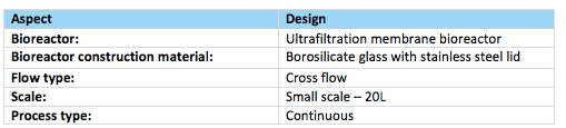
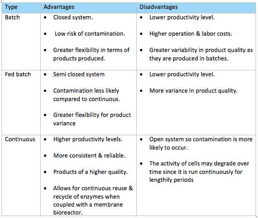
For our bioprocess we chose to use a continuous ultrafiltration membrane bioreactor as a membrane bioreactor is most commonly employed for peptide extraction via enzyme hydrolysis as the membrane acts as an immobilizing system entrapping the enzymes. There are three main types of processes which we could of chose from and they are batch, fed-batch and continuous (fig. 13). The team decided a continuous bioreactor would best suit our bioprocess which is a type of open system. Enzyme, substrate and other harvesting metabolites will be continuously fed into the bioreactor at regular intervals while simultaneously a corresponding flow of protein hydrolysates will be discharged at the other end thereby keeping a constant volume within the bioreactor at all times (Brethauer & Wyman, 2010). Although batch/ fed batch reactors are more widely used by industries, they do have several drawbacks such as lower productivity levels as time is required between each batch to perform tasks like emptying, cleaning, sterilizing & refilling the reaction vessel. Batch-to-batch variability of products is also likely to occur as the process is stopped after each batch and fresh media & cells are pumped into the reaction vessel each time.
Since our bioprocess uses a membrane bioreactor & enzymes both of which are relatively more expensive than other processes such as microbial fermentation in a standard bioreactor, employing a continuous process can justify this cost as it is more suited for the purpose of our bioprocess which is based on enzyme hydrolysis as it can run for lengthily periods without being stopped and discarding the enzymes each time after the vessel empties so in this way instead the enzyme can be continuously recycled & reused. Other reasons why we decided on a continuous type bioreactor rather than batch types are because the continuous process allows for better control and regulation of cell activity and product production (University of KwaZulu-Natal, 2011). Higher productivity levels can be achieved because enzyme, substrate & other harvesting metabolites are constantly fed into the reaction vessel unlike in batch production tasks such as sterilizing, cleaning, emptying & refilling the bioreactor are required to be performed after each batch which proves to be time-consuming. Furthermore, a continuous bioreactor results in more consistent, better quality products which are more reliable than those produced by batch type reactors. This is because they are continuously being produced rather than in batches which increases the likelihood of variability in product characteristics. Despite these desirable advantages a continuous bioreactor offers, it is more prone to contamination since it is an open system whereas a batch reactor is a closed system, therefore a high standard of hygienic practices must be maintained by workers and extra care has to be taken when preparing the bioreactor, substrate and harvesting metabolites to ensure complete sterility of the bioreactor & the inputs.
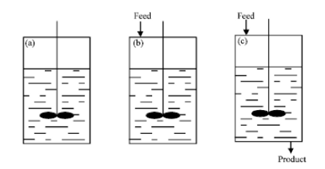
Figure 13. Types of bioreactors (a) batch (b) fed-batch and (c) continuous (Rashid, Hizbullah, & Khan, 2012)
Table 6. Summary of different types of bioreactors
Bioreactor Construction Material
The predominant materials used for the construction of a bioreactor include stainless steel, glass and plastic. Using plastic as a bioreactor is a questionable subject and was one we ruled out. Although they are single-use meaning time would be saved as processes such as cleaning & sterilization don’t need to be performed after each run, plastic is more prone to leaching which would essentially cause the material inside the bioreactor to be contaminated. This is something we want to avoid since our bioprocess is continuous, contamination would mean large volumes of product may be lost as a result which can be financially damaging for the company. It goes without saying that stainless steel bioreactors are the most common in industrial applications as they can be reused and are a chemically resistant material. Glass type bioreactors also confer similar advantages to that of stainless steel in terms of ease of sanitation, chemically resistant and their reusable nature. Additionally, this material is less proned to scratches so the likelihood of it harboring dirt is much less, the material itself is durable & lasts a lifetime and the transparency of the glass means the hydrolysis process inside the bioreactor can be visually monitored & observed for contaminants from the outside which are the principal reasons we chose this material for the construction of the bioreactor for our bioprocess particularly since our process is continuous the transparent property of glass would overall allow for greater control over the process.
The ultrafiltration (UF) membrane bioreactor will be composed of a special type of glass known as borosilicate glass and have a stainless steel lid as in figure 14. Borosilicate glass unlike ordinary glass is one manufactured with silicia, boric oxide and other alkalis such as sodium, potassium and aluminium oxide. As a result is it capable of withstanding high temperatures upto a maximum of 515oF (melting point: 550C) and is also highly resistant to expansion and thermal shock when exposed to heat (Qorpak, 2017). Our product will be produced on a small scale of 20L and will run for a lengthily period of time before being stopped emptied, cleaned, sterilized and reloaded for another run.
Figure 14. Borosilicate glass bioreactor with stainless steel lid steel lid (Broadley James, 2015)
Table 7. Summary of bioreactor construction material
Table 6. Summary of pros & cons of different bioreactor construction materials

Bioreactor Components
An ultrafiltration membrane bioreactor has two principle components – a reaction vessel where the enzymatic hydrolysis of the raw material will occur. This will contain the homogenized meat waste suppressed in an aqueous enzyme solution of pronase. Connected to the reaction vessel is a membrane system in a closed circuit as in figure 15.
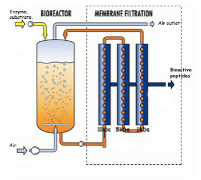
Figure 15. Ultrafiltration membrane bioreactor for production & isolation of bioactive peptides (Triqua International, n.d)
Additional components required in our bioreactor are as follows:
Table 8. Summary of bioreactor components

Headplate:
The head plate is essentially the upper lid of the bioreactor and will be composed of stainless steel. It will have ports for inlet of:
-
pH probe electrode
-
Dissolved oxygen probe
-
Temperature probe
-
Antifoam probe
-
Sample port (off-line investigation)
-
Sterile air
-
Feeding media (meat substrate, sterile water)
-
Cells (Pronase SAN)
-
Nutrients (magnesium, potassium, casein)
-
Acid (citric acid) & base (brine)
-
Antifoam agent (lard oil)
The lid will be screw connected to the body of the bioreactor and also have a silicone O-ring between to ensure air tight sealing. Blind stoppers will be used to seal any entry ports when not in use which will be screw in and each of the stoppers will also have a silicone O-ring fitted , again to ensure an air tight seal (fig. 17).
Figure 16. Stainless steel head plate with ports for inlets (Broadley James, 2015)
Figure 17. Blind stoppers for inlet ports (Broadley James, 2015

Figure 18. Design of head plate (Fauzan et al., 2012)
Agitator:
The agitator is the apparatus responsible for mixing the contents of the reaction vessel, it consists of impellers which are the rotating component (blades) positioned on a shaft. This is required in our bioreactor to help keep the enzymes suspended while also maintaining a homogenous environment to ensure an even distribution of heat, enzyme, oxygen, acid/base, nutrients and other harvesting metabolites. The shaft is essentially a long rod which transmits torque & rotation to the impellers. It will enter the bioreactor from the top and will operate at a speed of 600rpm. Impellers come in a variety of different shapes and sizes as seen in figure 19.
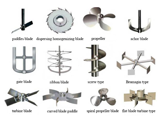
Figure 19. Types of impeller blades (Su, 2017)
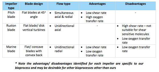
For our bioprocess, pitch blade impellers will be employed which consist of three flat type blades position at a 45 degree angle (see figure 20.). The design of these impellers results in a low shear rate thus they allow for gentle mixing of the bioreactor contents without causing any major disruption to cells or other molecules within the reaction vessel (Mirro & Voll, 2009). This is the desirable aspect which makes this impeller type most applicable for our bioprocess because the recovery of bioactive peptides from the meat substrate first involves the use of enzymes which are known to be shear sensitive and thus a high shear rate could potentially result in their inactivation & a loss of enzyme activity. Furthermore, proteins form an essential part of our substrate which are necessary for sourcing our product (bioactive peptides) from. A high shear rate could consequently lead to potential denaturation & insolubility of proteins which are problems we are looking to minimize to ensure a high peptide yield (Winkler, 1990).
Other impellers which were in consideration were both Ruston type and gentle marine blade impellers. Although one of the most common impeller blades used in industry, Ruston impellers, because of the number of flat vertical blades, result in a high shear rate hence they are not considered suitable for shear sensitive cell lines & components like those involved in our bioprocess. Marine blade impellers then have quite a similar design to the chosen pitch blade impellers and are also commonly utilized for applications requiring gentle mixing & a low shear rate but their unidirectional flow pattern means they lead to a lower oxygen mass transfer rate in comparison to pitch blade impellers (Mirro & Voll, 2009). Therefore, pitch blade impellers were opted for because the combination of their flat blades at 45o angles produce simultaneous radial and axial type flows and so more consistent efficient mixing is achieved as well as a higher oxygen mass transfer rate (fig. 22).
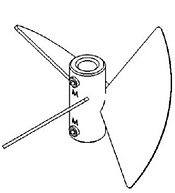
Figure 20. Pitch blade impeller (Mirro & Voll, 2009)
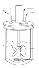
Figure 21. Impeller & shaft design (Carvalho et al., 2017)
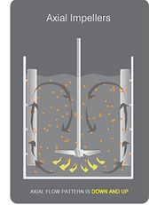
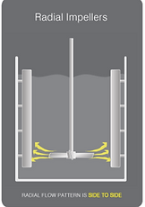
Figure 22. Axial & radial flow patterns (Dynamix, n.d.)
Table 9. Summary of different impellers considered
Baffle
Four stainless steel baffles will be welded to the inner walls of the glass bioreactor each spaced 45o evenly from eachother. When the process will be scaled up in the future requiring a larger bioreactor size then more baffles will be introduced but for now four is sufficient enough for the size of the bioreactor being used. Baffles are essentially referred to as elongated obstructing plates. We decided to include these in the bioreactor to prevent a whirl pool effect occurring in the reaction vessel during agitation which could potentially impede mixing while simultaneously helping create a more turbulent flow (fig. 23). The diameter of the baffles will approximately be one tenth of the diameter of the reaction vessel and will be placed at a minimum distance as possible from the vessel wall in order to minimize the harboring of dirt and microbial growth on the walls of the vessel.

Figure 23. Mixing patterns without baffles and with baffles (Peters, 2015)
Sparger
A sparger will be included in the bioreactor in order to introduce gases into the reaction vessel mainly oxygen, small amounts of carbon dioxide will be introduced as it has antibacteriostatic properties and thus will help minimize the occurrence of bacterial growth in the vessel which is important in our case as our bioprocess uses meat which is prone to bacterial contamination and the conditions of the reaction vessel are within close proximity of the conditions which favor bacterial growth on this substrate. The supply of oxygen into the vessel will also help assist mixing of the contents therefore reducing the overall power required to move the agitator to achieve an appropriate level of mixing. The type of sparger the team has chosen is a stainless steel ring sparger. This is a kind of perforated pipe in the shape of an open ring and it will be positioned below the pitch blade impellers at the bottom of the reaction vessel as in figure 24. Pressure will be applied to force out gas bubbles which will flow in an upward direction and into the headspace in the bioreactor and the gas will then be removed by being passed out through the air outlet. The approximate size of the sparger will be three quarters the size of the impeller. Holes in the sparger pipe will be 6mm in diameter as any smaller tends to become blocked and so the introduction of gas into the vessel will be interrupted in this case. The sparger holes will also be facing downwards in order to minimize retention of particulates in the holes. (Jagani et al., 2010).
Other spargers employed in bioreactors include porous and nozzle type. Porous spargers tend to only be used in vessels without an agitating system and their small holes are more prone to blocking. A nozzle sparger consists of a single or many nozzles coming from a central pipe delivering gas. All types are efficient at introducing gas into the vessel but the simple reasoning a ring sparger was opted for was because of its greater efficiency at distributing gas (Raj & Karanth).
Figure 24. Production of gas from sparger into headspace of vessel (K., 2011)


Figure 25. Stainless steel ring sparger (bbi Biotech, 2015)
Cooling Jacket
A cooling jacket will be placed around the reaction vessel in order to control the temperature of the environment of the bioreactor which is important in order to ensure optimum activity of the enzymes which occurs at 40C. Agitation and reactions within the vessel may lead to a rise in temperature and so it needs to be regulated as too high of a temperature could result in enzyme inactivation. This will be achieved by placing an external cooling jacket around the vessel in which glycerol will serve as the coolant and be passed through the jacket to regulate the temperature. If additional heat is required to bring the temperature back upto its desired range then heated water will be passed through the jacket in this case as in figure 27.
Condenser
A condenser will be used to help minimize the loss of material from the reaction vessel via evaporation which will consist of two ports – an inlet port and outlet port for supply of cold water. Cool water will be passed through the inlet which will then cools & condense any air leaving the vessel into water droplets which will then return to the reaction vessel.

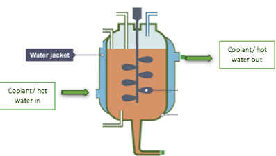
Figure 27. Working principle of cooling jacket (Nelson, 2016)
Figure 26. Cooling jacket (Bioprocess Control AB, 2016)
Control Systems
During any type of reaction, it is vital to ensure the process is constantly under control and that the environment within the bioreactor is maintained at optimal conditions for maximum activity and product production. This involves continually monitoring parameters such as pH, temperature, nutrient concentration, oxygen and foam levels. The enzymes required for the generation of bioactive peptides from meat waste we will use both have identical optimum conditions – pH 8 and 40C with SAN requiring 0.5% Salt and magnesium while pronase requires 0.5% casein & potassium. Control sensors which will be included as part of our bioreactor include:
Temperature probe – This will be used to monitor the internal temperature of the reaction vessel to ensure its maintained at 40C for optimum enzyme activity. Coolant and heated water will be used to regulate the temperature of the vessel through the external coolant jacket,
Antifoam probe – This will be used to measure the level of foam in the vessel. Agitation within the bioreactor can lead to the formation of foam in the reaction vessels headspace which is undesirable as it can lead to leakages, loss of material and contamination if the volumes become excessive. Foam formation is liable to happen in our bioprocess since the mixture within our bioreactor will be rich in protein which are essentially suspectable to aeration when mixed producing a froth/ foam. Once the foam level reaches the antifoam probe it will trigger the pumping of small amounts of antifoaming agent into the vessel. The antifoaming agent which will be used in our system is lard oil which is natural and is manufactured from pig fat and so it can be produced onsite from the pig waste. Oils help reduce foam by reducing the surface elasticity (Jagani, et al., 2010).
Dissolved oxygen probe – This will be used to measure the levels of dissolved oxygen in the bioreactor which is important for foam control and cell activity.
pH probe – This will be used to periodically check the pH of the environment of the bioreactor to ensure it is maintained at pH 8 for optimum enzyme activity. If the pH proves to be too acidic, an alkaline substance will be added and vice versa.
A 0.5% brine solution will be used as the alkali as it will help increase the pH if too low and additionally will help form a favorable environment for one of our enzymes – SAN – which requires a high salt environment for maximal activity. Citric acid will be used as the acid as it is commonly utilized in conjuction with meat on a daily basis and is therefore compatible with the substrate but also it is naturally occurring having been obtained from citrus fruits and so this makes it even more ideal for application in our bioprocess as our aim is to generate the bioactive peptides with natural substances to avoid using harsh chemicals as the resulting product is proposed at being free from all synthetic substances and is intended for oral administration.
Pressure gauge - This device will be used to measure the pressure of the environment within the bioreactor to ensure its maintained and doesn’t exceed too much that it could cause bursting of pipes or other problems. It is also important that the pressure level is maintained at a constant level from a microbiological perspective – the pressure gradient helps ensure microorganisms are prevented from gaining entry into the vessel as they struggle to overcome this barrier thereby helping keep a sterile environment within the vessel.
Rotameter – This device will be included as part of our bioreactor in order to monitor the flow rate of liquids, air & gases into the reaction vessel.
Filters
Inlet & exhaust filters will be employed for our bioreactor in order to minimize possibility of contamination by ensuring air & gases entering and leaving the vessel environment are sterile. Since such filters will be used a filter housing is also a necessity to act as a storage cabinet for the filters where they will be sterilized and maintained until further use. This component is vital as it helps assure complete sterility of filters.
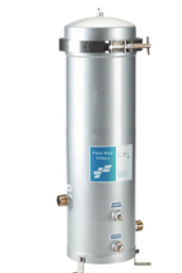
Figure 28. Filter housing (Flow Max Filters, n.d)
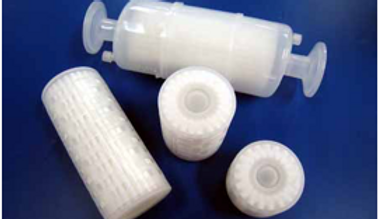
Figure 29. Filters (ZenPure, 2017)
4. Preparation of bioreactor
Prior to inoculation for the of the bioprocess, our bioreactor requires to be set up and undergo a series of cleaning stages before it can be used to ensure it is in a sterile condition and free from contamination (see fig. 30).

Figure 30. Stages of bioreactor set up
Clean-in-place
The first stage in preparing the bioreactor for use is clean in place also known as CIP. It is a cleaning cycle consisting of a series of detergent washes and water rinses to remove any dirt, excess product or organic debris from all surfaces of the vessel which resulted from the previous batch. For each stage, the CIP solutions will be injected into the bioreactor through the ring sparger employed in our bioreactor and a spray ball mounted near the top of the bioreactor. The spray ball will be composed of stainless steel and have holes positioned all around to ensure maximum coverage of all areas of the bioreactor with cleaning solutions. This device will run at a low pressure of 2 bars. The bioreactor system will be cleaned under turbulent flow conditions with a flow velocity of 2.0 m/s.
CIP unit
For our cleaning in place, a carefully controlled CIP unit will be use as this is vital for our process considering it uses a series of membranes so the cleaning process can be closely controlled and it assures that any cleaning chemicals or parameters used for the cycle don’t cause irreversible damage to the membranes which would prove costly for Nutri plus.
The CIP unit will consist of :
-
Tanks – for fresh water, recovered water, acid and caustic (alkali).
-
Supply pumps – For supplying the cleaning solutions. Filters will be applied on each supply line to minimize the occurrence of blockages.
-
Recirculation loops – for recirculation of cleaning solutions/ water.
-
Temperature loops – For control of temperature of acid/ alkali
-
Temperature probes – to monitor the temperature of each stage to ensure the desired temperature of each step is reached
-
Conductivity transmitters - for monitoring the concentration of acid and alkali being used
-
Conductivity probes – for detecting any possible interferences which may occur between water the acid/ alkali solutions in the return lines of the CIP unit
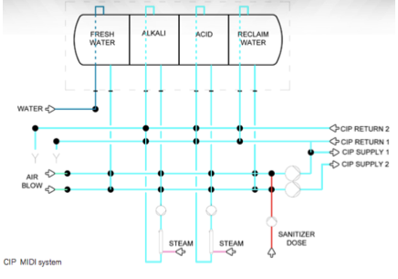
Figure 31. CIP unit model (SPX, 2013)
Our CIP procedure will consist of a combination of the following steps:

Figure 32. CIP cycle
1. Initial rinse
The bioreactor will be initially rinsed with recovered water from the final flush of the previous CIP cycle to drain any residue from the system resulting from the previous batch. By using water from the previous cycle, this will help us minimize water usage to an extent. This step will last for a duration of 5 mins at a temperature of 25C.
2. Caustic wash
Next is the caustic wash which is the first major wash of the CIP cycle for removing debris from the bioreactor. CIP 100 alkaline detergent will be used for this wash. This is a type of high performance phosphate free alkaline detergent made with potassium hydroxide and a blend of surfactants, chelants and other performance-enhancing ingredients (VWR, 2016). This specific detergent was chosen due to its low foaming properties and its broad activity spectrum meaning it will ultimately remove nearly all soils & residue which may be present. This stage will be performed at 85C for 30 mins.
3. Intermediate rinse
An intermediate wash will then be performed using fresh water to simply wash and drain out the alkaline solution from the bioreactor system. This step will be performed at 25C and last for a duration of 5mins.
4. Acid wash
The next major wash of the CIP cycle will then take place, this is known as the acid wash which will be used to remove any mineral residue/ scale from the surfaces. CIP 200 acid detergent will be used for this wash which is a high performance phosphoric acid cleaner. Its blended composition of acids & surfactants make it capable of removing a vast range of scales and inorganic soils which is the principal reason the team decided to use it. This step will be performed under temperature conditions of 70C for a duration of 20 mins.
5. Final rinse
Another intermediate rinse will be performed with fresh water at 25C following the acid wash to wash out any remaining acid and other cleaning solutions remaining in the system. This will last for a duration of 10 mins.
6. Sanitation
The bioreactor will then be sanitized with WFI water at 85C for 15 mins. WFI water is a type of highly purified water containing less that 10 CFU/100ml of aerobic bacteria and is specifically used for making injectable drugs or any component which may come into contact with a product intended on being a drug.
Setting up
Once the bioreactor has been adequately cleaned the probes, valves, inlet & exhaust filters and filter housing will be set up.
Filters
The inlet & exhaust filters are an important aspect in our bioprocess as they ensure complete sterility of gases/ air entering & exiting the bioreactor. They will be set up ensuring to be properly fitted and visually inspected for any visible cracks or damage which may cause leakages. The o-ring silicone seals will also be double checked to ensure they are intact.
Probes
The different probes will then be set up. Our bioprocess uses Medorex pH, temperature, dissolved oxygen and antifoam probes all of which play an essential role in monitoring the environment of our bioreactor to ensure conditions are maintained at optimum for an efficient process. Each of the probes are autoclavable. Prior to installation in the bioreactor, each of the probes will be calibrated accordingly. The probes are screw in type and will be carefully screwed in place in the appropriate ports ensuring not to damage the electrodes in any way. Once all probes have been put in place they will be double checked to ensure they are intact properly.

Figure 33. Screw in temperature probe (Medorex, 2016)
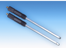
Figure 34. Screw in pH probe (Medorex, 2016)
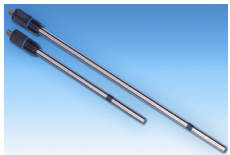
Figure 35. Screw in dissolved oxygen probe (Medorex, 2016)
Valves
Prior to the pressure hold test then the valves will be set up which are used to control flow through the ports. It is a requirement that these are installed before the pressure hold test and SIP cycle as the pressure hold test will tell us if there are any leakages from the valves and the SIP cycle will sterilize the valves to free them from any trace of contamination before beginning the bioprocess.
Pressure hold
A pressure hold test will then be performed to check the integrity of the bioreactor. Pressurized gas will be supplied to the bioreactor to the recommended level by the manufacturers. This pressure level will be held for several minutes then the gas will be shut off and the pressure drop will be monitored as a function of time. If the pressure drop value proves to exceed the maximum value stated then this is an indication a leakage is present in the system which needs to be addressed and the bioreactor cannot be used until it passes the pressure hold test.
Steam-in-place

Figure 36. Steam-in-place cycle
Once the bioreactor successfully passes the pressure hold test the steam-in-place sterilization cycle will begin (SIP). This is essentially the killing of microorganisms through the application of moist heat in the form of steam under pressure. There are three main stages in the SIP cycle we have designed for our bioreactor and they are as follows:
1. Pre-conditioning
This stage involves preparing the vessel for sterilization. The bleed valves will be open and any air, condensation and gas will be bled from the vessel. These valves will remain open for the SIP cycle to eliminate condensate. Pressurized air will be applied to dry the system & filters to assure adequate steam flow. Heated steam will then be supplied to gradually heat the system for the SIP.
2. Sterilization
Once the temperature probes indicate the desired sterilization temperature (121C) is reached the SIP cycle begins and will be help for 30mins. During the sterilization process, the temperature & pressure will be constantly monitored to ensure steam remains saturated throughout the whole process for adequate sterilization. The inlet & exhaust filters are steam sterilized at the same time as the vessel through the open valves. The sterilization process will be validated based on the temperature recorded of the exiting steam. If it is below 121C the SIP cycle will be repeated until satisfactory.
3. Post-conditioning
Once the SIP process is complete, the steam valves will be closed and the pressurized steam and condensate will be removed from the system through drain valves by pressurized air to assure no steam condensation is left behind as this could consequently result in the creation of a vacuum (Cappia, 2004). The temperature will be decreased and coolant will be run through the bioreactor cooling jacket to assist the cooling process until a temperature of 40C is reached which is the temperature required for our bioprocess.
Media Fill
Following a satisfactory SIP cycle, the bioreactor will then be ready to be filled with the appropriate media which for our bioprocess required for the activity of pronase & SAN. This is an mixed aqueous solution of 0.5% brine & 0.5% caesin, magnesium and potassium which will be added in through the sterile media filters which have been sterilized during the SIP cycle and will be added up to the desired working volume is reached. While the media solution is being filled into the vessel, the pressure gauges and vessel weight will be monitored as trend changes in either of these two aspects could be an indication of a blockage or clogging occurring. After each fill, the media filters will be disposed of as they are only single-use.
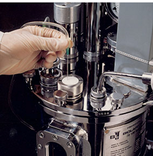
Figure 37. Injection of media in through media filters (QualiTru, 2017)
5. Inoculation
After the vessel has been filled to the appropriate volume with the required media, the homogenized meat substrate will be fed into the bioreactor through the feeding inlet in the lid. Prior to inoculation the conditions of the bioreactor will be checked to ensure they are at optimum, then inoculation with pronase & SAN enzymes through the sample port will take place to initiate the bioprocess. Upon inoculation, the enzyme hydrolysis process begins. From this point on substrate, enzymes and other harvesting metabolites will continuously be fed into the bioreactor as our process is continuous.
Enzyme hydrolysis, in layman terms, is when a protein is broken down into its respective peptides also including the release of a water molecule. In the case of our bioprocess two enzymes are in action.
WHats happening in the Bioreactor?
6. Enzyme Hydrolysis
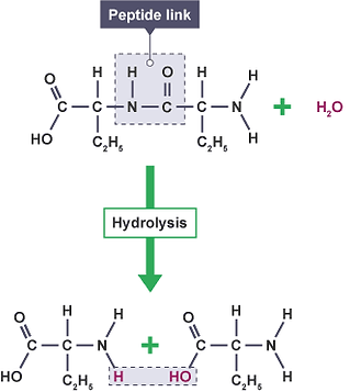
Figure 38. A schematic describing protein hydrolysis. (BBC, 2017)
As our target peptides are dormant in the parent protein, they must be activated by an essential means of release. This “release” occurs through enzyme hydrolysis. The enzyme used for hydrolysis in this project is pronase which will essentially cleave all proteins present within the meat substrate and break the peptide bonds in the parent protein to free the peptides for extraction. An additional enzyme SAN will also be inoculated into the vessel. The purpose of this enzyme is to remove DNA molecules that are produced as a result of the protein being broken down. In this way, it will help reduce the viscosity of the mixture in the reaction vessel which in turn will help minimise the occurrence of blockages & clogging and increase the ease of mixing.
During this enzyme hydrolysis process 0.5% brine, 0.5% casein, potassium and magnesium will be fed in accordingly to the vessel as they are the nutrients required by the enzymes for efficient activity. At regular intervals, the temperature, pH and level of dissolved oxygen and foam will be measured to ensure they are maintained at optimum levels.
The resulting protein hydrolysates harvested in the reaction vessel will be directly passed from the bioreactor into the multichannel ultrafiltration membranes through piping connecting the membranes and bioreactor in a closed circuit to being the downstream purifcation and recovery of our product.


References
bbi Biotech. (2015). Bioreactor parts. Retrieved Novemeber 30, 2017, from bbi Biotech: http://bbi-biotech.com/en/shop/all/
BBC. (2017). Bitesize: proteins. BBC. Retrieved on 1st December 2017, from https://www.bbc.co.uk/education/guides/zswqq6f/revision/2.
Bhat, Z.F., Kumar, S. & Bhat, H.F. (2015). Bioactive peptides of animal origin: a review. Journal of Food Science and Technology. 52(9), 5377 - 5392.
Bioprocess Control AB. (2016). Bioreactors. Retrieved November 20, 2017, from Bioprocess Control: http://www.bioprocesscontrol.com/products/bioreactors/
Brethauer, S., & Wyman, C. (2010). Review: Continuous hydrolysis and fermentation for cellulosic ethanol production. Bioresource Technology, 101, 4862–4874.
Broadley James. (2015). Bioreactor assembly. Retrieved November 2, 2017, from Broadley James: https://www.broadleyjames.com/product/15-liter-bioreactor-assembly-jacketed-cell-culture/
Broadley James. (2015). BioReactors. Retrieved October 23, 2017, from Broadley James: https://www.broadleyjames.com/product/20-liter-bioreactor-assembly-microbial-fermentation/
Dynamix. (n.d.). Mixing 101: Flow Patterns & Impellers. Retrieved November 30, 2017, from Dynamix: http://www.dynamixinc.com/mixing-101-the-basic-principles-of-mixing-and-impellers
Fauzan, E. &. (2012). Parts of a bioreactor. Retrieved October 5, 2017, from Mr Bioreactor: http://bioreactoritumenarik.blogspot.ie/2012/12/in-first-day-meet-mr.html
Iveta. (2017). If you ever feel sad these 10+ highland cattle calves will make you smile. Boredpanda.com. Retrieved on 1st December 2017, from https://www.boredpanda.com/cute-baby-highland-cattle-calves/.
K., R. (2011). Techniques of Recombinant DNA Technology | Essay | Biotechnology. Retrieved November 30, 2017, from Biology Discussion: http://www.biologydiscussion.com/essay/biotechnology-essay/techniques-of-recombinant-dna-technology-essay-biotechnology/75913
Mirro, R., & Voll, K. (2009). Which Impeller Is Right for Your Cell Line? Retrieved October 15, 2017, from BioProcess International: http://www.bioprocessintl.com/analytical/cell-line-development/which-impeller-is-right-for-your-cell-line-183538/
Peters, S. (2015). Introduction to Mixer Impellers & Flow Patterns. Retrieved November 30, 2017, from Crane Engineering: https://blog.craneengineering.net/introduction-mixer-impellers-flow-patterns
Nelson, M. (2016, May). Makingbiologyeasy. Retrieved November 20, 2017, from IGCSE Biology: http://milliemakesbiologyeasy.blogspot.ie/2016/05/58-interpret-and-label-diagram-of.html
Qorpak. (2017). What is Borosilicate Glass? Retrieved October 23, 2017, from Qorpak A Division of Berlin Packaging: http://www.qorpak.com/pages/whatisborosilicateglass
Raj, A., & Karanth, N. (n.d.). Fermentation Technology and Bioreactor Design. In A. Pometto, K. Shetty, G. Paliyath, & R. E. Levin, Food Biotechnology (2nd ed., pp. 67-76). CRC Press.
Rashid, M. M., Hizbullah, N., & Khan, M. (2012, January). Advanced Control Technique for Substrate Feed Rate Regulation of a Fed Batch Fermentation. Asian Journal of Biochemistry, 7, 1-15.
Ryan, J.T., Ross, R.P., Bolton, D., Fitzgerald, D.F., & Stanton, C. (2011). Bioactives from muscle sources: meat and fish. Nutrients. 3, 765 - 791.
Scientia. (2014). In the life of a micro-pig. Scientia. Retrieved on 1st December 2017, from https://www.freedawn.co.uk/scientia/2014/12/09/in-the-life-of-a-micro-pig/.
Su, S. (2017, July). KOSbest. Retrieved November 15, 2017, from Principle and Types of Agitator Stirrers: http://www.emulsifyingmixer.com/blog/principle-and-types-of-stirrers/
University of KwaZulu-Natal. (2011, February). Biological Sciences. Retrieved November 11, 2017, from University of KwaZulu-Natal: http://microbiology.ukzn.ac.za/Libraries/MICR304/TYPES_OF_MICROBIAL_CULTURE.sflb.ashx